Procedure for operating hydrophore
Initial start and adjusting (see figure below)
1. Open water inlet valve, start the pump 1 to add water to the pressure tank. Fill in water till it appear inside the glass tube of the level gauge 11
2. Open air charging valve 5. Fill in compressed air till the pressure gauge shows required pressure P1 (which depends on the piping system and the installation height of pump, normally it is between 2.5 and 3 bar)
3. Adjust the pressure switch 8 to required pressure range
4. Check connection of the pressure switch 8 to the pump 1 control circuit
6. Turn on the power of the pump 1
7. Open water outlet valve and release some water
8. Observe the value of the pressure gauge 7 when the pump starts, it should be about P1
9. Observe the value of the pressure gauge when the pump stops, it should be about P1 + 1.25…2 bar
10. Release some water and check the value of the pressure gauge again.
11. Observe the time from the pump starts to it stops.
After hydrophore unit working automatically.
Periodically during watch recommended to check the value of the pressure gauge, water level in the glass level gauge, absence of leakages etc.
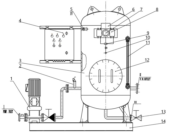
Hydrophore unit general view
I – pump inlet, II – FW outlet, III – drain outlet, IV – air inlet, 1 – centrifugal pump, 2 – safety valve, 3 – pressure tank, 4 – control box, 5 – air charging valve, 6 – name plate, 7 – pressure gauge, 8 – pressure switch, 9 – seat, 10 – valve, 11 – glass level gauge, 12 – manhole cover, 13 – drain valve, 14 – base plate