Procedure for Operation of the Domestic Fresh Water System
The following procedure is with one FW tank (No1 Port) and one FW pump (No1) in use.
a) Check that there is sufficient water in the domestic FW tank to meet the immediate demand.
b) With the hydrophore tank not under pressure open one of two FW storage tank outlet valve (FG04V or FG05V) and relative FW pump suction valve (FG08V or FG09V) and the pump outlet valve to hydrophore tank. Start the pump manually in local control and fill it until the water level gauge glass is ¾ full (75 % of hydrophore tank capacity) then stop the pump. Open the air valve and pressurise the hydrophore tank to the correct operating pressure. The outlet from the hydrophore tank, valve FG10V, must be closed at this time.
c) With the hydrophore tank up to pressure and at the
correct level put one domestic FW pump in AUTOMATIC mode at the control panel
and allow it to cut in and out as required in order to maintain pressure in the
system and level in the tank. The hydrophore outlet valve FG10V can be opened
and FW can be supplied to the various users.
In case of filling FW tank (No2 Starboard) from the FWG outlet valve FG05V
should be closed.
d) With the fresh water hydrophore tank in operation set valves as in the following order (see figure below): crossover valve to the drinking water system from the fresh water hydrophore tank FG55V should be closed; freshwater mineraliser crossover valve from the fresh water hydrophore tank FG53V should be closed; freshwater line valve to cold water accommodation system FG11V and freshwater line valve to hot water make-up FG32V open.
e) Open the engine room services valves as required, for instance, if necessary to supply water near high sea chest need to open FG28V valve, or to provide water for ME turbocharger washing need to open FG41V valve, see figure below.
f) Periodically check level in hydrophore tank and add compressed air as required.
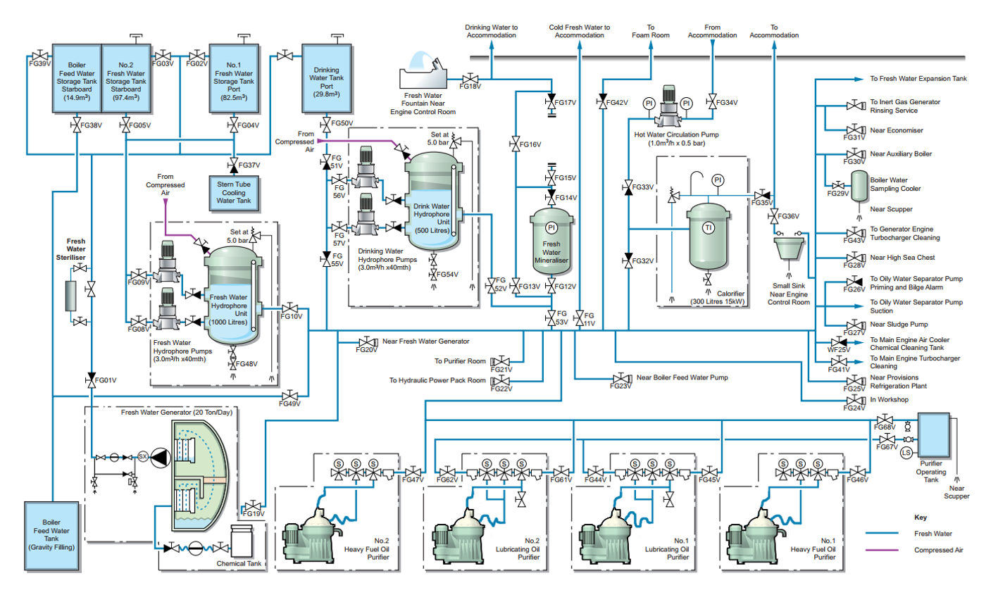
Domestic freshwater system
of a tanker vessel