FWG plant membrane type
Membrane type RO FWG plants mainly uses on board of cruise ships first of all due to their high capacity and energy efficiency (production capacity 10…3000 m3/d/vessel, energy consumption 2,4…4,0 kWh/m3 of freshwater) compared to conventional freshwater systems. One of the world´s leading manufacturers of reverse osmosis systems for cruise ships is WatMan. Below provides description of working principle and figures of lay out and process diagram based on WatMan RO 45000 SW 2-pass reverse osmosis FWG plant.

a b
Lay out of WatMan RO 45000 SW 2-pass reverse osmosis FWG plant, up view (a) and side view (b)
1 – heating water circulating pump, 2 – heat exchanger, 3 – energy recovery turbine, 4 – 2-pass RO unit, 5 – RO unit elements (1st and 2nd pass membranes), 6 – multimedia (sand) filters
WatMan RO 45000 SW 2-pass reverse osmosis FWG plant double-pass plant with energy recovery by turbine. Its capacity is 1070 m3/day (44,6 m3/hour). The plant consist of one seawater centrifugal pump, six WatMan MLFA 48 Multimedia filters, two sets chemical dosing units, one heat exchanger (plate type, heating water / seawater (hot/cold)) unit, one 2-pass RO unit (First pass: spiral wound thin film composite low energy membranes Seawater SW30 by Filmtec or equivalent - 84 pcs; Second pass: Spiral wound thin film composite membranes Brackish water low energy membranes by Filmtec or equivalent - 42 pcs, hydraulic pressure booster, high pressure feed pump, flow meters, pressure gauges, conductivity controller, automatic fresh water flushing system, draw-back tank) and one electrical control cabinet.
Seawater pump supply raw water to the set of WatMan MLFA 48 Multimedia filters (six filters to be installed in parallel). Multimedia filter filings shown in the figure below. Then after filters water going to heat exchanger which maintain appropriate temperature before RO unit. Meanwhile one chemical dosing unit automatically adds (before multimedia filters) NaHSO3 for disinfection of raw water and another one adds (between heat exchanger and RO units) Ameroyal 642 or equivalent for RO membrane antiscaling.

Multimedia filter filings
1 – support layer of gravel (Ø 2…3 mm / 300 l), 2 – 1st filter layer of sand (Ø 1…2 mm / 100 l), 3 – 2nd filter layer of sand (Ø 0.5…1.0 mm / 300 l), 4 – 3rd filter layer of aqua-volcano (Ø 1.5…2.5 mm / 600 l), 5 – empty space
In RO unit water passes membranes of 1st pass and after 2nd pass (see figure below). 1st pass high pressure pump increases pressure up to 30…40 bar before RO unit 1st pass. Then water flow through hydraulic pressure booster (which boost pressure up to 50 bar by recover energy of reject flow) going to 1st pass membranes. After 1st pass 60 % of incoming water rejects by membranes (through HBP to overboard) and 40 % water (TDS 200…400 mg/l) supplies by high pressure pump under pressure up to 16 bar to the 2nd pass. After 2nd pass the freshwater with quality TDS < 20 mg/l going to FW tank.

Source: https://www.watman.fi/pages/en/sea-water-desalination
WatMan RO 45000 SW 2-pass reverse osmosis FWG plant process diagram
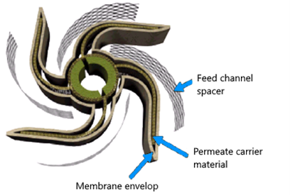
Figures below illustrates a simplified spiral wound RO membrane element. The spiral wound RO membrane is constructed of one or more membrane envelops wound around a perforated central tube. The permeate passes through the membrane into the envelop and spirals inward to the central tube for collection.

Simplified spiral wound RO membrane
element

Cross section of a simplified membrane element

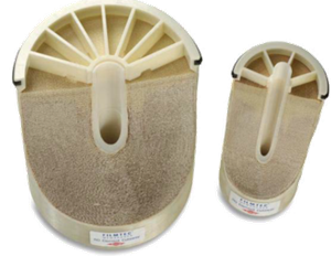
Transversal cut of a Filmtec spiral wound RO membrane element
