Arranging the air handling unit control panel for low-speed and minimum air circulation and heating
This method is applied in cases where minimum ventilation with low-speed air flow is necessary. In such an application, command elements of the panel (Fig.24) and AHU (Fig.25) are arranged by Marine Engineer.
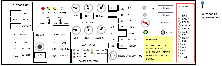
Figure.24 Air handling unit control panel arranged for low-speed, minimum air circulation and heating
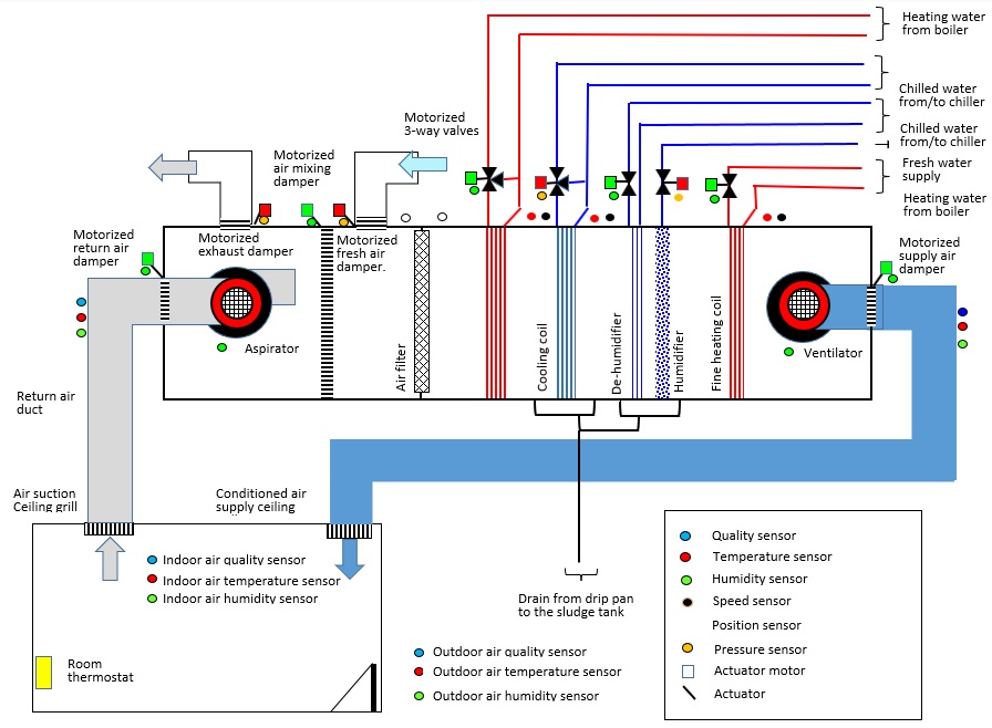
Figure.25 Air handling unit running for low-speed and minimum air circulation and heating
Table. 8 Command-and-control elements on panel arranged for 100% air circulation and cooling
Sq. Element Setting/Monitoring Condition
1. Command Shift Power switch ON
2. Control Monitor Power lamp lits WHITE
3. Control Monitor Phase lamps lit RED, GREEN, YELLOW
4. Control Monitor Alarm lamps lit WHITE
5. Command Set control switch MAN
6. Command Set AHU start time 20h 30m
7. Command Set AHU stop time 06h 30m
8. Control Monitor outdoor air temperature 32 oC
9. Control Monitor outdoor air humidity 80%
10. Control Monitor outdoor air quality 35%
11. Command Set room thermostat temperature 21
12. Command Set room air humidity 55%
13. Command Set room thermostat air quality 80%
14. Command Set RAD 100%
15. Control RAD opens and lits 100% , GREEN
16. Command Set EAD 0%
17. Control EAD opens and lits 0% , RED
18. Command Set FAD 0%
19. Control FAD opens and lits 0% , RED
20. Command Set SAD 100%
21. Control SAD opens and lits 100% , GREEN
22. Command Set MAD 100%
23. Control MAD close and lits 100%, GREEN
24. Command Click on button START
25. Control Monitor START button lits GREEN
26. Control Monitor Aspirator voltage analog 380
27. Control Monitor Aspirator voltage digital 380
28. Control Monitor Aspirator current analog 15
29. Control Monitor Aspirator current digital 15
30. Control Monitor Aspirator speed analog 250
31. Control Monitor Aspirator speed digital 250
32. Control Monitor Ventilator voltage analog 380
33. Control Monitor Ventilator voltage digital 380
34. Control Monitor Ventilator current analog 15
35. Control Monitor Ventilator current digital 15
36. Command Set Aspr. and Vent. fan speed 250
37. Control Monitor Ventilator speed analog 250
38. Control Monitor Ventilator speed digital 250
39. Control Monitor Heating valve motor lits GREEN
40. Control Monitor Heating valve lits GREEN
41. Control Monitor Cooling valve motor lits RED
42. Control Monitor Cooling valve lits RED
43. Control Monitor Humid valve motor lits RED
44. Control Monitor Humid valve lits RED
45. Control Monitor De-humid valve motor lits GREEN
46. Control Monitor De-humid valve lits GREEN
47. Control Monitor last heating valve motor GREEN
48. Control Monitor last heating valve lits GREEN
49. Control Monitor outdoor Temperature 32
50. Control Monitor outdoor air humidity 80
51. Control Monitor outdoor air quality 35
52. Control Monitor return air temperature 28
53. Control Monitor return air humidity 70
54. Control Monitor return air quality 65
55. Control Monitor air filter-in pressure 1.1
56. Control Monitor air filter-out pressure 1.2
57. Control Monitor heating coil-in temp. 18
58. Control Monitor heating coil-out temp. 21
59. Control Monitor cooling coil-out temp. 21
60. Control Monitor humidity 55
61. Control Monitor Supply air temperature 21
62. Control Monitor Supply air humidity 55
63. Control Monitor Supply air quality 80