FWG plant maintenance
The maintenance schedule of FWG plant presented in the table 1 and shows how often service should be performed on the main components.
FWG Alfa Laval JWP-26-C Overhaul intervals
|
Component |
Operating Hours |
Action |
|
Evaporator section |
As required |
Clean in inhibited acid bath |
|
Condenser action |
As required |
Clean with pure freshwater and brush |
|
Separator vessel with anodes |
2000 h |
See separator instructions |
|
Combined ejector/cooling water pump with motor |
8000 h |
Measure seal ring and impeller. |
|
Freshwater extraction |
8000 h |
See above |
|
Combined air/brine ejector |
8000 h |
Measure nozzles and diffuser and compare
to measurements in technical specification. |
|
MV-valves |
4000 h |
Disassembly and inspect for damage |
|
8000 h |
Clean in inhibited acid bath |
|
|
Manometers |
8000 h |
Adjust with control manometer |
|
Salinometer |
1000 h |
Remove electrode unit and inspect/clean. Use a clean and dry rag. Avoid touching the electrodes with the fingers. |
Maintenance of Separator Vessel
The front cover and the pressure plates for the heat exchanger sections (evaporator and condenser) are made of stainless steel with a special chemical treatment. This treatment will re-establish normal surface oxidation after work-up at the factory. The preparation is a natural protection of the stainless steel. To preserve this natural protection don’t scraper scratch the inside surface of the front cover.
Whenever the separator vessel is opened, check that the anodes are functioning. If the anodes are not functioning and/or scarified, replace them.
If the unit is stopped for a longer period than 14 days.
- open front covers and clean unit inside with freshwater.
- let the unit dry out completely, before closing covers.
Maintenance of Evaporator Section
Clean evaporator as follows:
1. Remove bolts in front cover, and open.
2. Loosen the 4 nuts in plate stack gradually, so that no nut is carrying the entire load alone.
3. Remove plate stack.
If some of the gaskets come loose on removing plate stack, please see section “Cleaning”.
4. Submerge plates completely in a hot, inhibited acid bath at maximum 50 ºC. For further instructions see “Chemical dosing of scale control chemicals”.
5. Examine plates and gaskets for possible damage, and remove damaged plates and/or replace damaged gaskets.
6. If a defective plate
is found, remove the plate together with one of the adjacent
plates.
The assembly measurements must be reduced with 3.5 mm per plate, if plates are removed from plate stack.
The first one and the last one plate of the evaporator plate stack (marked as EE and ES correspondingly) cannot be removed but must always be replaced with a corresponding plate.
7. Reassemble evaporator section in accordance with assembly scheme.
8. Tighten plate stack to measurements stated in technical specification.
9. Pressure test evaporator section before closing front cover. The evaporator section is pressure tested by letting hot water circulate through the section with bypass valve for hot water in normal running position.
10. When the evaporator
section is found to be tight, close front cover and tighten bolts.
11. Retighten cover, when vacuum has been re-established.
Maintenance of Condenser Section
Clean condenser as follows:
1. Remove bolts in front cover, and open.
2. Loosen the 6 nuts in plate stack gradually, so that no nut is carrying the entire load alone.
3. Remove plate stack.
If some of the gaskets come loose on removing plate stack, please see section “Cleaning”.
4. Scrub plates with a soft brush and plain hot water at maximum 50 ºC.
5. Examine plates and gaskets for possible damage, and remove damaged plates
and/or replace damaged gaskets.
6. If a defective plate is found, remove the plate and one of the adjacent plates.
The assembly measurements must be reduced with 3.5 mm per plate, if plates are removed from plate stack.
The first one and the last one plate of the condenser plate stack (marked as KE and KS correspondingly) cannot be removed but must always be replaced with a corresponding plate.
7. Reassemble condenser section in accordance with assembly scheme.
8. Tighten plate stack to measurements stated in technical specification.
9. Pressure test condenser section before closing front cover.
The condenser section is pressure tested by letting sea water from the combined cooling water/ejector pump circulate through the section.
Before starting the combined ejector/cooling water pump, the feed water must be sealed off.
10. When the condenser section is found to be tight, close front cover and tighten bolts.
11. Retighten, when vacuum has been re-established.
12. Do not forget to remove the feed water sealing as mentioned above.
Renewal of Plate Heat Exchanger Gaskets
Removal of Old Gaskets
Pull the old gaskets out of groove. If the gasket cannot come off directly, heat the back of the gasket groove with a hot-air blower or butane gas burner. Pay attention not to overheat the plates. You will obtain a suitable temperature, if the flame is held 10 to 15 cm behind the plate.
Cleaning
Charred or loose glue and
rubber remains must be removed, e.g. using a rotating stainless steel brush.
The width should be adapted (Ø 40…50 mm, width 8…10 mm). Thin layers of glue which are difficult
to remove, may remain. Clean the gasket groove with a clean cloth, dipped in a
solvent (acetone, methyl ethyl ketone, trichlorethylene etc.).
Gaskets, that have loosened, can be glued on. Clean gasket groove carefully with a sharp tool. Then clean the loose part of the gasket with emery cloth or sandpaper. Finally clean groove and gasket with a solvent, and glue.
Preparation of New Gaskets
Dry new gaskets with a clean cloth that has been slightly moistened with a solvent.
Fitting New Gaskets
1. Apply a thin layer of glue to both gasket and groove.
2. Let the glue dry for 10…15 minutes.
3. Fit new gasket into groove.
Gaskets may sometimes be slightly short or long. Short gaskets should be stretched before being fitted into the groove. Long gaskets should be fitted into the grooves at the plate ends first and then gradually be pushed into the groove towards the middle. If necessary, tape gasket into groove.
Chemical Dosing of Scale Control Chemicals
Prevention of Scaling
During the evaporation of sea water there is always a risk of scaling on the heating surfaces. This will lead to a reduction of the K-values of the heating surface and decreasing freshwater production and reduction of plant efficiency. In order to effectively prevent scaling the engineers must be aware of the factors influencing the scale formation.
Feed Water Ratio
The feedwater ratio is an extremely important factor. It is defined by the relationship between the feedwater amount fed into the plant and the produced amount of freshwater. If the feedwater ratio is reduced, the concentration will rise in the plant subsequently resulting in scale formations. Two things may shift the feedwater ratio: first of all direct adjustment of the feedwater system, and secondly exceeding the maximum freshwater production laid out for the plant. The engineers must observe the following rules at all times.
Chemical Dosage
In order to control scale formations on the heating surfaces and continuously ensure long operation periods without acid cleaning the plant, it is absolutely necessary to dose scale control additives to the feedwater.
If the FWG is operated at boiling temperatures above 45 °C without chemicals, frequent cleaning of the evaporator will be necessary. Do not operate the FWG without recommended chemical dosage at boiling temperatures above 45 °C. Even at lower temperatures it can be recommended.
Scale Inhibitor Dosage Equipment for Feed Water (figure below)
When adding chemicals mix thoroughly to ensure a homogenous blend of chemicals and water. Use a fully soluble scale inhibitor, e.g. on polymer basis.
1. Mix the required
quantity for 24 hours operation in the tank according to maker’s instructions.
2. Adjust flowmeter to cover the maximum freshwater output from the FWG.
3. Flush the dosage system regularly.

1 – flowmeter including regulating valve, 2 – nipple, 3 – non-return valve, 4 – hose connection, 5 – hose clip, 6 – hose, 7 – adapter, 8 – fitting, 9 – fitting, 10 – ball valve, 11 – tank
Safety Precautions with the use of Chemicals
1. Use eye protection and
gloves. Avoid direct skin contact, eye contact or contact with clothes.
2. Clean empty containers before disposal.
3. If chemicals are spilled on clothes, rinse with water and dispose off clothes.
4. If chemicals are spilled on the floor, rinse with water and suck remaining chemicals off with sand. Clean the spot immediately afterwards.
5. Scale inhibitor is hazardous, if consumed in a concentrated solution.
If consumed by mistake immediately seek medical attention.
6. If eyes get in contact with the chemicals, rinse for at least 20 minutes.
Maintenance of Freshwater Pump
Overhaul of the Pump (figure below)

Freshwater pump cross-section
1 – washer, 2 – pump casing, 3 – countersunk screw, 4 – gasket, 5 – impeller, 6 – pump cover, 7 – mechanical shaft seal, 8 – screw, 9 – shaft complete, 10 – screw, 11 – screw, 12 – key, 13 – wear ring, 14 – plug
1. Remove the screws 11 on the pump casing 2.
2. Lift motor with pump cover 6 and impeller 5 clear of pump casing 2.
3. Unscrew countersunk screw 3 (right hand thread).
4. Remove impeller 5. Normally, it can be removed without using dismantling tools.
5. Remove key 12.
6. Remove the mechanical shaft seal 7.
7. Inspect the ceramic ring, the carbon ring and the spring.
8. Replace mechanical shaft seal, if necessary. It is recommended to grease the shaft and seat for the ceramic ring with glycerine in order to make it easier to assemble the mechanical shaft seal. Please also observe separate instructions for mechanical shaft seal delivered together with the seal.
9. Fit carbon ring, spring and spring holder on pump shaft.
10. Inspect impeller and the drilled sealing water channel for clogging, and clean.
11. Remember to replace gasket 4.
12. Reassemble in reverse order.
Clearance
In connection with the inspection be sure to measure the impeller and wear ring 13 in order to secure that the clearance is no more than 0.5 mm on the diameter.
The pump shaft 9 must only be dismantled, if pump shaft or electric motor bearing has to be replaced.
Dismantling Pump Shaft
1. Dismantle the pump as described above.
2. Unscrew pointed screws 10.
3. Carefully insert two screw drivers behind the pump shaft, and loosen it. If the pump shaft does not come loose, use the special dismantling tools shown in figure below.

Dismantling tools for pump shaft
1 – screw, 2 – nut, 3 – washer, 4 – disc 5 – pipe, 6 – pump shaft
The tool consists of a
pipe 5, a disc 4 with hole for the screw 1 and a nut 2, washer 3 (figure above).
The length L must be longer than the length l. Place pipe around
the shaft. Fasten the screw with nut and washer into the threaded hole M12 on
the shaft end. Loosen shaft by tightening the nut while holding on to the
screw.
4. Mount the new pump shaft on the motor shaft.
5. Make sure that the pump shaft fits the motor shaft without any obstructions, before final shaft fitting as follows, tap onto the end of the pump shaft slightly with a rubber hammer.
6. Tighten pointed screws as follows (figure below):

Checking procedure the wobble of the pump shaft with a dial gauge
The torque should be 5 Nm and the maximum wobble 60 µ.m.
7. Check the wobble of the pump shaft with a dial gauge.
8. Assemble the pump as described above.
Maintenance of Ejector Pump
Overhaul of the Pump (figure below)

Ejector pump cross-section
1 – screw, 2 – wearing ring, 3 – key, 4 – screw, 5 – pump cover, 6 – screw, 7 – shaft complete, 8 – screw, 9 – motor bracket, 10 – screw, 11 – spring washer, 12 – mechanical seal, 13 – O-ring, 14 – wear ring, 15 – impeller, 16 – pump casing
1. Remove the set screws 10 in pump cover 5.
Motor with motor bracket 9, pump cover 5,
and impeller 15 can now be lifted clear of the pump casing 16.
2. Unscrew the screw 1 (right-hand thread).
3. Remove impeller.
Normally, the impeller can be removed without using dismantling tools. If not, you can fit dismantling screws into the two threaded holes in the impeller.
4. Remove the key 3 and the mechanical seal 12 (including spring holder, spring and carbon ring).
5. Inspect the ceramic
ring, the carbon ring and the spring. Replace, if necessary
If mechanical seal has to be replaced, proceed as follows:
- unscrew set screw 6 to remove pump cover 5 from motor bracket 9 in order to gain access to ceramic ring. In order to make it easier to assemble the mechanical seal, the shaft and ring seat may be greased with glycerine
- after fitting the ceramic ring, fit pump cover 5 to motor bracket 9.
- fit carbon ring, spring and spring holder.
6. Clean drilled cooling water channel in pump cover 5.
7. Inspect impeller and threaded holes for clogging.
8. Remember to change the O-ring 13.
9. Reassemble in reverse order.
Clearance (figure below)
In connection with the inspection, the impeller 15 and wear ring 2 are measured in order to secure that the clearance is not larger than stated in the diagram below.
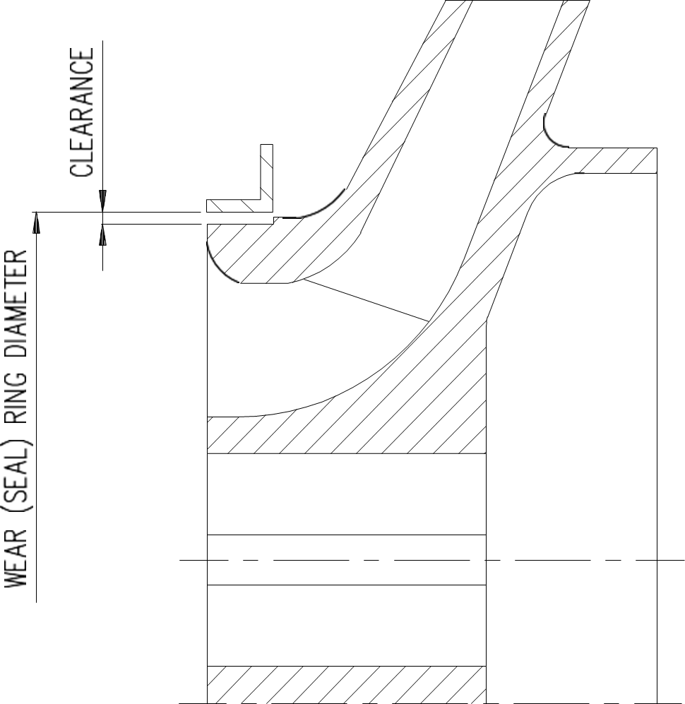
Clearance
between wear ring and impeller
Clearance measuring
|
Wear ring Ø |
Clearance maximum |
Clearance minimum |
|
100 mm |
0.5 mm |
0.15 mm |
|
150 mm |
0.6 mm |
0.2 mm |
|
200 mm |
0.7 mm |
0.25 mm |
|
250 mm |
0.8 mm |
0.28 mm |
|
300 mm |
0.85 mm |
0.3 mm |
|
350 mm |
0.9 mm |
0.3 mm |
If the clearance is too big, replace wear rings as follows:
1. Unscrew countersunk screws 4.
2. Pull out wear (seal) rings.
3. Fit new wear rings and tighten countersunk screws.
The pump shaft may only be dismantled, if pump shaft or bearings, in the electric motor have to be replaced.
Dismantling Pump Shaft
If the shaft 7 has to be dismantled due to a defect or if electric motor bearing has to be replaced, proceed as follows:
1. Unscrew pointed screws 8.
2. Remove shaft 7. Normally this can be done without using dismantling tools.
3. Fit shaft 7.
4. In order to make sure that the coupling is fitted correctly, tap slightly at the shaft end with a rubber hammer.
5. Tighten pointed screws 8 with a torque of 35 Nm.
FWG plant with shall-and-tube type of heat exchangers SASAKURA KM 30
The maintenance and inspection schedule of FWG with shall-and-tube type of heat exchangers plant presented in the table below.
FWG SASAKURA KM type maintenance & Inspection
|
Item |
Component |
Contents |
Intervals |
|||
|
Every month |
Every 3 months or 2,000 hours |
Every 6 months or 4,000 hours |
Every 12 months or 8,000 hours |
|||
|
Heater |
Inside of heater pipes |
Rinse by following the instructions in this Instruction Manual. |
|
|
O |
|
|
Inside of bottom lid |
Check for damage and pinhole on the coating. Repair, as necessary, by following the instructions in this Instruction Manual. |
|
|
|
O |
|
|
Feed water pipe |
Feed water orifice |
Clean, and confirm the inside diameter. |
|
|
|
O |
|
Cooling pipe |
Check for erosion state on the pipe ends. Check if there is scaling inside the pipe, and rinse as necessary. |
|
|
|
O |
|
|
Tube plate |
Check for flaw and erosion. If any irregularity is found, correct it. |
|
|
|
O |
|
|
Condenser water box corrosion bar |
Inspect the state of installation and degree of abrasion. Replace, as necessary. |
|
O |
|
|
|
|
Inside of condenser water box |
Check for damage and pinhole on the coating. Repair, as necessary, by following the instructions in this Instruction Manual. |
|
|
|
O |
|
|
Coating surface |
Inspect. If repair work is necessary, repair by following the instructions in this Instruction Manual. |
|
|
|
O |
|
|
Deflector and mesh separator |
Inspect. If a problem is found, correct it. Check if there is scaling, and rinse as necessary. |
|
|
|
O |
|
|
Glass |
Clean. |
|
|
O |
|
|
|
Water ejector |
Nozzle and inside surface of diffuser |
Inspect and clean. Replace the excessively worn or damaged nozzle or diffuser with a new one. |
|
|
|
O |
|
indicator |
Cell (electrode) |
Carefully clean the salinity indicator, being careful not to damage the electrode. |
|
O |
|
|
|
Ejector pump |
Impeller |
Clean and inspect. |
|
|
|
O |
|
Casing ring |
Clearance of 2.3 mm or less. |
|
|
|
O |
|
|
Mechanical seal |
Inspect or replace. |
|
|
|
O |
|
|
|
O-ring |
Inspect or replace. |
|
|
|
O |
|
|
Impeller |
Clean and inspect. |
|
|
|
O |
|
Casing ring |
Clearance of 1.2 mm or less. |
|
|
|
O |
|
|
pump |
Mechanical seal |
Inspect or replace. |
|
|
|
O |
|
|
O-ring |
Inspect or replace. |
|
|
|
O |
Leakage test for the FWG
Perform a leakage test after the FWG has been opened up for inspection, or it fails to maintain the rated degree of vacuum. For this purpose, fill air into the evaporator and maintain the internal pressure in the evaporator at 0.05 MPa. Then, apply soap water onto the gasket and joint to detect a leaking point.
For testing, remove the evaporator vacuum gage or fully close the main valve.
Pressure Test for the Condenser and Heater
1. Cooling pipe and tube plate
Remove the condenser water box, fill air into the evaporator and maintain the internal pressure in the evaporator at 0.05 MPa. Then, apply soap water onto the gasket and joint to detect a leaking point.
2. Heating tube and tube plate
Remove the heater lower cover, and apply a water pressure of 0.53 MPa to the shell to detect a leaking point on the expanded tubes. Detect a crack or pinhole on a tube by forming a film of soap water and apply an air pressure of 0.05 MPa to the shell to allow a possible leaking point to be apparent.
If a problem such as a hole occurs on a heating tube, do not remove the tube in question, instead, plug the hole. Remove tubes only when replacing them with new ones. Spacer pipes are provided outside certain heating tubes to secure the baffle plate. For this reason, if the broken heating tube is removed, the spacer tubes around it can come loose and the baffle plate is no longer securely locked. The locations of spacer tubes vary depending on the FWG type.
Cleaning the Heat Exchanger Tube (Removing the Scale)
Timing for rinsing
The FWG contains the heater, condenser and feed water preheater. Scaling typically occurs inside the heating tube. Boiling and evaporating feed water readily generates scale inside the heater. The recommended intervals for rinsing inside the heating tube are two or three times per year. However, depending on the frequency of operation with the FWG and/or characteristics of seawater it handles, the intervals for rinsing the heating tube can vary. As a guideline, rinse the heating tube when any of the following situations occurs:
1. The freshwater generation rate has been gradually decreasing to below the 70 % the rated capacity.
2. The temperature difference across the inlet and outlet of hot water at the scheduled flow rate has dropped to 70 % or less as low as the planned difference.
3. The salinity has rapidly increased, and remains unstable for a long time.
If any of the phenomena above occurs, remove the sight glass on the front face of the evaporator, and insert the scale checker (included as a standard tool) into the heating tube as far as it goes. If the scale checker fails to go into the heating tube, scale of thickness 1 mm or greater has deposited inside the tube. If this case occurs, immediately rinse inside the heating tube.
As long as the FWG is run under normal conditions, much scaling does not occur in the cooling pipe of the condenser. However, that chemical cleaning of all the piping system is possible by installing the adaptor (optional) to the corrosion-proofing plate seat in the condenser water box.
Method for rinsing
There are two categories of methods available for scale removal:
1. Physical stripping. This category includes scale removal with a brush or drill, and scale removal with high pressure water jet. However, scale removal with these techniques is highly difficult.
2. Chemical cleaning. Scale removal techniques using a cleaning agent are available. The methods using a cleaning agent that efficiently removes scaling are described below.
Preparation for rinsing
1. Close the feed water adjust valve (1)
2. Drain away the feed water in the equipment through the bottom blow valve (2).
3. Fully open the bottom blow valve (2), and open up the sight glass on the evaporator.
Preparation for cleaning agent
In a drum can, prepare a solution of cleaning agent necessary for cleaning the FWG. To prepare the dilution, be sure to pour water first, and then add the concentrated cleaning agent.
Rinsing by immersion
Through the opening formed after the sight glass is removed, pour in the cleaning solution until the tube plate in the upper portion of the heater is immersed with the liquid. Allow the liquid to stand. The necessary cleaning time varies depending on the thickness of scale. When reaching saturation, the cleaning solution loses its cleaning power. Therefore, it will be necessary to replace with fresh cleaning solution several times.

FWG heater rinsing by immersion
Rinsing by circulation
By referring to the figure below, install the special adapter to the seat for corrosion bar on the cooling water inlet on the condenser water box. Use this adapter as the inlet for cleaning solution and the bottom plate of the FWG as the outlet for cleaning solution. With this arrangement, rinse the whole piping system in the heat exchanger of the FWG by circulating the cleaning solution.
Draining the cleaning solution
Drain the cleaning solution away from the bottom blow valve (2). By referring to the instructions in the instruction manual supplied from the cleaning agent manufacturer, neutralize and dispose the drained cleaning solution.
Flushing the FWG to complete rinsing operation
After draining away the cleaning solution, flush the whole FWG system with seawater. Then, feed cooling water to the condenser to fill the FWG and discharge the feed water overboard through the water ejector. Repeat this cycle until the inside of the FWG system is clean.

FWG heater rinsing by circulating
Inspection after the rinsing operation
Scaling most often occurs on an area at approximately 1/5 to 1/4 the distance from the lower tube plate to the tube plate. Through the opening remaining after removal of the slight glass, lower the "Scale checker" sensor heads to several lower points on the heating tube and scan the heating tube to check that the entire inside surface of the heating tube has been satisfactorily cleaned.
For this rinsing work, do not use steam because the inside surface of the evaporator is covered with a coating.
Method for prolonging rinsing intervals
To prolong the rinsing intervals as long as possible, observe the following instructions for operation of the FWG:
1. Whenever possible, run the FWG below the rated water generation capacity.
2. Continuously inject the scale inhibitor into the feed water by using the chemicals injection unit.
3. Feed water as much as the discharge capacity of the water ejector permits.
4. Do not run the FWG in a dirty sea area such as in a bay.
5. When shutting down the FWG, feed water until the heater shell is cool enough and the operator can touch the heater shell by hand to allow the heater to be filled with fresh (not concentrated) seawater up to the heater top tube plate.
Repairing the coating on inside surface
If damage on the coating on inside is found in the course of inspection on the FWG, repair according to the next sequence. Remove the damaged coating layer, thoroughly dry the exposed surface, polish the coating layer up to the area 20 mm apart from the rim of exposed steel surface as well as the exposed steel surface with a piece of emery paper, and then rinse the whole polished area. After the problem area has been dried, add the hardening agent to epoxy resin in a vessel in appropriate proportion. Once stirred, epoxy resin begins curing in approximately 40 minutes at a room temperature (approximately 30 °C). For this reason, when intending to applying a second layer onward, do not open the cans for the epoxy resin and hardening agent until next coating application is possible. After a previous layer has been fully cured (it will take approximately 6 hours), apply next layer. Form a total of three layers. Allow the repaired area to stand for 1 or 2 days at a room temperature until the area becomes fully dry.
Very carefully handle the epoxy resin and hardening agent. In the case of skin contact, immediately wash away with a plenty of water.
Reverse osmosis FWG plant WatMan RO 45000 SW 2-pass
Typically, the unit PLC informs about all the necessary measures to be taken. Some of the actions must be taken beforehand. The PLC messages have been divided as follows:
Warning signal: the system cannot operate for long periods without service.
Alarm signal: the system
cannot operate properly and must be automatically
stopped.
Warning signals:
1. If the system will be stopped because of overboard valve closed (0) signal, warning “Overboard Valve Closed” will be given.
Procedure:
Open the valve.
Check the switch and wiring.
2. LSA2.1 – at the low level of
chemical tanks, a warning is given: “No Sodium Bisulfite”
Procedure:
Add chemical according to point 5.
Check the level switch and cabling.
3. PDSA3.1 - Warning is connected to
“High pressure loss / Wash multimedia filters Warning”.
Procedure:
The pressure loss of the filters is too high and the filters are
fouled/clogged.
Wash the filters manually by pressing the suitable knob.
Change (lower down) the filter run sequence from the PLC.
The filter run sequences have been too long.
The water quality is poor. Check the water quality.
Check the level switch and cabling.
4. PDSA5.1 - Warning connected to “High pressure loss / Change filter bags Warning”.
Procedure:
The pressure loss of the bag filter is too high and the bags are fouled/plugged.
Change the bags at the earliest possible convenience.
The water quality is poor. Check the water quality.
Check the media filters. Change (lower down) the filter run sequence from the PLC
Change the filtering media of the media filters (after some years).
Check the level switch and cabling.
6. PC6.1 - Operating minimum P is 45 bar (default). If the limit cannot be reached, a “Low Operating Pressure” warning will be given.
Procedure:
Not enough water is flowing in.
Too much water is flowing into reject.
Not enough pressure is given by the high-pressure pump.
Not enough pressure is given by the variable frequency drive.
Seawater temperature is extremely high.
Check the seawater line.
Check the seawater feed pump.
Check the media filters.
Check the bag filter.
Check the influent pressure after bag filter.
Check the high-pressure pump.
Check the variable frequency drive, adjust if necessary.
Check the pressure transmitter.
Check the reject line and flow.
Check the HPB (turbo).
Check the reject line valve AV6.4.
Check the reject line flow transmitter.
7. QT6.1 - EC is higher
than set-point value, a “Bad Water Quality” warning will be given.
Procedure:
Change the settings of the freshwater conductivity limits.
Check the seawater quality.
Check the reject line flow.
Clean and check the conductivity meter, change the measuring cell.
Clean the membranes/system according to Cleaning.
Change the membranes.
8. FT6.3 – Fresh water flow is lower than expected, a “Low Fresh Water Flow” warning
will be given.
Procedure:
Not enough water is flowing in.
Too much water is flowing into reject.
Not enough pressure is given by the high-pressure pumps.
Not enough pressure is given by the variable frequency drives.
Seawater temperature is extremely low.
Check the seawater line.
Check the seawater feed pump.
Check the media filters.
Check the bag filter.
Check the influent pressure after bag filter.
Check the pressure by the high-pressure pumps, adjust if necessary.
Check the variable frequency drives, adjust if necessary.
Check the fresh-water line flow transmitters.
Check the pressure transmitters.
Check the reject line and flow.
Check the HPB (turbo).
Check the reject line flow transmitter.
The membranes are fouled, clean the membranes/system according to Cleaning.
Change the membranes.
9. FT6.2 – Reject flow to overboard/drain is lower than expected, a “Low Reject Flow Problem” warning will be given.
Procedure:
Not enough water is flowing in.
Not enough pressure is given by the high-pressure pump.
Not enough pressure is given by the variable frequency drive.
Check the seawater line.
Check the seawater feed pump.
Check the media filters.
Check the bag filter.
Check the influent pressure after bag filter.
Check the pressure by the high-pressure pump, adjust if necessary.
Check the variable frequency drive, adjust if necessary.
Check the pressure transmitter.
Check the reject line and flow.
Check and adjust the HPB (turbo).
Check the reject line valve AV6.4.
Check the reject line flow transmitter.
10. Dp (pressure
difference) between PC6.1 and PT6.2 - If dP is higher than expected, a
“High Membrane dP; clean the system” warning will be given.
Procedure:
Too much water is flowing in.
Too much water is flowing into reject.
Seawater temperature is extremely low.
Check the freshwater line flow transmitter.
Check the reject line flow transmitter.
Check the pressure transmitter.
Check the reject line valve AV6.4.
The membranes are fouled, clean the membranes/system according to Cleaning.
Change the membranes.
11. Fouling Factor – If “Normalized flow” is lower than expected and “Fouling Factor”
lower than expected, “Prepare to clean the system” warning will be given.
Prepare to clean the system.
Reserve the clean-in-place chemicals.
Alarm signals:
Alarm signal: the system cannot operate properly and must be automatically stopped.
1. “System Alarm” will be given, if the high-pressure pump CP6.1 cannot be operated normally.
There are interlocks:
Interlock 1: valve MV/AV6.1 has been open for time (1) before the pump start-up. Time (1) default is 60 sec.
Interlock 2: valve AV6.4
has been open for time (1) before the pump start-up. Time
(1) default is 60 sec.
Interlock 3: pump CP1.1 must be running.
Interlock 4: Pressure PC6.1 is lower than dry-run set value.
Interlock 5: The pump
cannot start if "Cleaning phase" has been started and not
finished.
Interlock 6: Either AV/MV6.2 or AV/MV6.3 must be power-off (=closed) during start up and running.
Interlock 7: Pressure PC6.1 must be lower than high-pressure value.
Interlock 8: AV/MV7.2 must be power-off (=closed) during pump run.
For start-up in manual position:
Interlock 1: MV6.1 and AV6.4 must be opened.
Interlock 2: Pump CP1.1 must run.
Interlock 3: PC6.1 and PT6.1 switches off the pump if out of limits.
2. PC6.1 – Dry run - If PC6.1 is lower than minimum set value (default 6 bar), pump CP6.1 will stop and MV/AV6.1 close down. The system will stop and “Dry-run, low running pressure” alarm will be given.
3. PC6.1 – Overpressure - If PC6.1 is higher than max-value (default 65 bar), pump CP6.1 will stop and MV/AV6.1 close down. The system will stop and “High operating pressure” alarm will be given.
4. FT6.2 – When pump CP6.1 is running and reject water flow is lower than 20 m3/h, the system will stop. “Low reject flow problem” alarm will be given.
5. PT6.1 - If PT6.1 is higher than max-value (default 5 bar), pump CP6.1 will stop and the system will close-down. "High freshwater pressure" alarm will be given.
6. PT6.3 - If PT6.3 is higher than max-value (default 15 bar), pump CP6.1 will stop and the system will close-down. "High reject pressure after Turbo" alarm will be given.
7. PSA8.1 - If PSA8.1 pressure air line pressure is lower than 5 bars, the system will close-down. "Low Air Pressure" alarm will be given.
8. Fouling Factor – If “Normalized flow” is lower than expected and “Fouling Factor” lower than expected, the system will close down and the “Clean the system” alarm will be given.
Prepare to clean the system.
Reserve the clean-in-place chemicals.
Alarm reset button
Press to reset. Warning and alarm messages do not remove without resetting.
Daily routine actions
1. On a daily basis, inspect the entire system for leaks, and general condition.
2. If the pressure difference across the prefilters rises radically, the backwash frequency should be changed. Check that the backwash flow rate is stable.
Accepted pressure difference (head loss) for prefilters is [pure filter head loss] + 0.5…1.0 bars.
3. If the pressure difference across the bag filter rises above 0.5...1.0 bars, the bags should be changed. The exchange minimum is 4 times/year for each bag.
4. Take care that enough Na-bisulphite can be found in the chemical tank. Add if necessary, see point 1.
5. Take care that enough antiscalant can be found in the chemical tank. Add if found necessary, see point 1. Never run the system without antiscalant dosing! It may lead to irreversible membrane fouling.
6. The unit should give a message to prepare to clean the system and then to clean the system. Proceed according to separate instructions above.
If the chemical wash will not be made early enough and properly, a permanent loss of flux and flow rate can follow.
7. Always after cleaning check that you have another set of suitable cleaning chemicals available.
Monthly and annually routine actions
For the mechanical
maintenance, see enclosure “AMOS”. Proceed according to given instructions.
Check also:
(1) Service the pumps and the pressure tanks according to separate instructions by the pump manufacturer.
(2) Check the prefilter media amount, add if necessary. Change the media if found necessary and in any case after 3…5 years of use.
(3) Check the permeate quality and the flux/flow after a normal cleaning. If the flow or the quality cannot be reached, change the membranes. The default life span of the membranes is 3 – 5 years depending on the use.
Chemical wash
Chemical wash should be done if:
1. To achieve the same permeate flow, pressure should be risen 10 - 15 % from the initial pressure.
2. With the same initial pressure permeate flow will drop more than 15 %.
3. Permeate quality is constantly poor.
4. Pressure drop across the membranes rises by 10 – 15 %.
5. The PLC informs to clean the system.
Procedure Warning!
1. Always use protective clothing, gloves and a face mask or a helmet visor.
2. Locate the emergency shower and an eye rinse bottle.
3. Thoroughly read through the safety information given of the chemicals (MSDS) – choose a suitable cleaning solution from the list afterwards. The solution depends on the type of foulant.
In severe fouling, the best result can be achieved by making the cleaning twice with the same liquid or by using both the washing liquids (A, first) and (B, second) one after another.
Before draining into natural waters, always take care of the neutralization of the spent cleaning chemicals. Normally pH 6-10 is allowed.
Typical chemicals are (A) 2 % Sodium Tripolyphosphate + 0,8 % EDTA solution (20 kg sodium tripolyphosphate + 8 kg EDTA in 1000 liters of water, pH adjusted to 11-12 with sulfuric acid)
- for iron, organics and silicate colloids
- for calcium sulfate
Corresponding trademarks:
Ultrasil-110, Ameroyal C800, Alkaline PermaClean
Ultrasil-110:
To reach pH level of 11 use 0,5 – 2 % liquid (= 5 - 20 kg Ultrasil-110 and 1000 liters permeate). Never exceed pH value of 12, however, the best possible effect is achieved very near to 11,5.
During the cleaning phase add more chemical if needed.
(B) 2 % Citric Acid solution (20 kg in 1000 liters of water, pH adjusted to 4,0 with ammonium hydroxide)
- for iron compounds
- for calcium carbonate
Corresponding trademarks:
Ultrasil-75, Ameroyal C238, Acidic PermaClean Ultrasil-75:
To reach pH level of 2 use 0,5 – 2 % liquid (= 5…20 kg Ultrasil-75 and 1000
liters permeate). Never let the pH value fall under 1.5 however, the best
possible effect is achieved very near to 1.5.
During the cleaning phase add more chemical if needed.
Never let the pH-value fall below of 1,5 (lowest acceptable limit) or exceed 12.0 (highest acceptable limit). Normal cleaning liquid temperature is 30…35 °C. Do not exceed this without special permission.
Chemical cleaning procedure
Reserve the cleaning agents as described in points (A) or (B). When started by pressing the clean start button, the cleaning itself is running automatically and controlled by the PLC. Follow the instructions given by the PLC display, and fill in the suitable chemicals as described above.